6 3D model reconstruction in Agisoft Metashape
6.1 Download Agisoft Metashape
Download the Agisoft Metashape professional edition software here. Make sure that your computer fills the minimum system requirements. The standard edition doesn’t allow the use of the scale option, which we will need to add a scale to our models.
Figure 6.1: Agisoft Metashape Logo.
6.2 Initial tweaks
Agisoft Metashape can use graphic cards at certain steps of the model construction such as image matching and depth maps calculation. To enable the use of the graphic hardware (GPU):
Select Preferences command from the Tools menu (v. <2.0) or MetashapePro menu (v. >2.0).
In Preferences dialog select GPU tab.
Select available GPU devices in GPU tab of the Preferences window.
This step has to be done only once.
This protocol has been elaborated using the version 1.7.1 of Agisoft Metashape. The latest version of Metashape is now version 2.0.3, but we still made the following changes. In order to obtain accurate thin structures, such as petal margin, and avoid holes in your mesh in Agisoft Metashape versions older than 2.0 (as far as we know) you will need to activate ONCE the Visibility consistent mesh function in Tools > Preferences > Advanced >Tweaks, then Add and fill in Parameters with BuildModel/tvl1_mesh and select the value as False (figure 6.2). Additionally, to use the anterior version of the depth maps generation process, add ONCE the tweak: BuildDepthMaps/pm_enable and set the value to False (figure 6.3). For Agisoft Metashape 2.0.x (as far as we know) the Preferences are located in the MetashapePro menu.
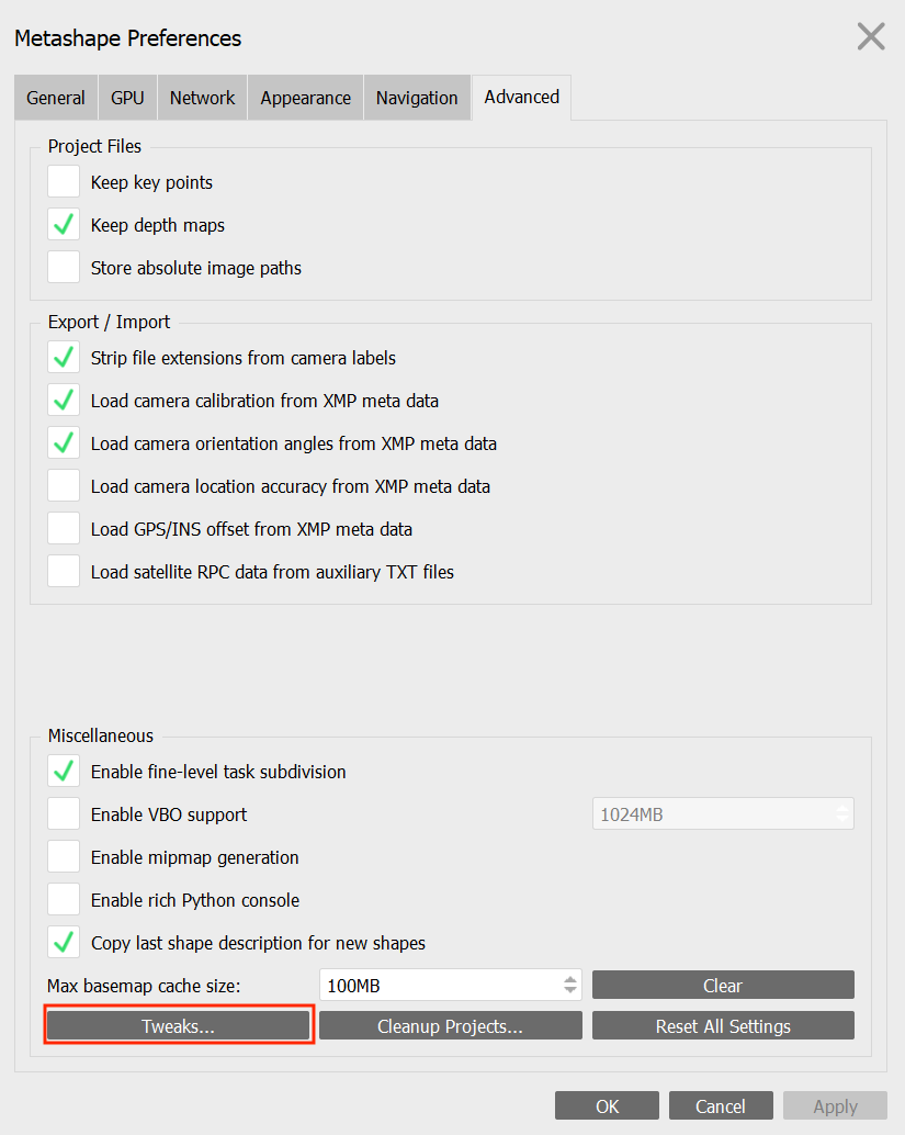
Figure 6.2: Tweaks settings (A).
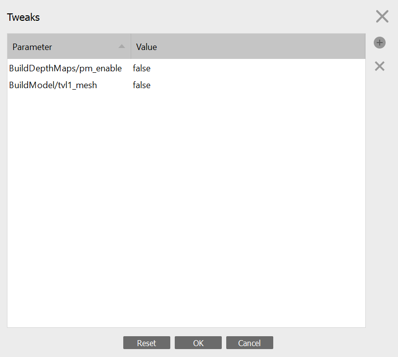
Figure 6.3: Tweaks settings (B).
6.3 Overview of the model building pipeline
To build a model, we need to do the following steps: (1) Import the calibrated photos, (2) Apply masks to remove the background of the photos, (3) Align the photos, (4) Calculate depth maps, (5) Build the 3D model (mesh), and (6) Reconstruct the final texture (model color). There could be different approaches for each of the steps and options will be given below.
One important thing to consider is whether to align all the photos simultaneously or proceed by groups of photos (i.e., “chunks”) that correspond to each flower position. The first approach is quicker and normally results in more accurate models. However, it does not work all the time. We recommend to try the first approach and if it fails, to use the alternative approach, which is to divide the pictures in different "chunks" that will create partial 3D models that will be subsequently merged.
6.4 Photo importation
Go to Workflow, click on Add Photos, and click Open. Once the photos are imported, they are in a single "chunk".
To try to align all the photos simultaneously (ideal approach), you need to arrange them in “Image Groups” ot “Camera Groups” (e.g., select the photos, right click, Move Images/Cameras > New Image/Camera Group)*, where each camera group contains all pictures taken with the same flower orientation and camera angle. Once this is done, you can add the first photo of each set of photos representing the label, right click on this photo and select Disable Cameras or Disable Images*. This allows you to not take it into account while reconstructing the model, but to keep all the information about the flower in your Metashape project.
*Note: Depending on the version of Agisoft Metashape, some functions use either the word “camera(s)” (v.<2.0) or “image(s)” (v.>2.0) as far as we know.
6.5 Mask application
Masks represent selected areas that are excluded from the feature detection procedure when applied to key points detection. When several keypoints are detected as the same point (matched as projections of the same 3D point on different photos), then it is considered as a tie point. If masks are applied to tie points, then if a key point is masked in at least one image, it will not be considered. You can thus use a single or just a few masks with the second method and apply masks to tie points. It is however possible to automatically apply masks on each photo to better constrain key point detection and then apply masks to keypoints. Using masks helps in removing points from being detected in the background during the image alignment procedure. You can see examples here on the Agisoft helpdesk portal.
Step-by-step mask application workflow
Duplicate one of your photos, and fill it in black (or the main color of your background) in any image manipulation software, and rename it to background.jpg or background.tif depending on the format of your photos. You can also take a picture of the lightbox without your flower just before starting to shoot and use this image as background. This sometimes work better.
Right click on a photo in one of your chunk in your Metashape project.
Click on Masks, Import Masks (Figure 6.4) and in the box that appears select the method From Background and operation Replacement.
Enter the same name as the name of the background image you created in step 1.
Depending on the flower and how contrasting its color is relatively to the background, the value for Tolerance can vary between approximately 40 and 60 (Figure 6.5). For some pale flowers you may need a lower tolerance value (e.g. 30 or lower).
Test different values of tolerance on a single photo first and when you have a value that is satisfactory (i.e., that creates a mask with the border of the flower well defined), you can select Apply to > Entire workspace.
Click OK.
This will automatically produce masks around the flowers for all the photos in all your chunks. This is why we need a contrasting background color behind the flower.
Check for masks that need touch ups (see next section).
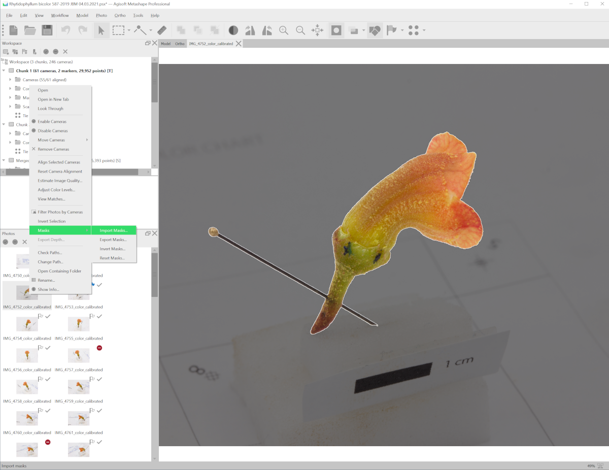
Figure 6.4: Right click on an image to select a mask to import.
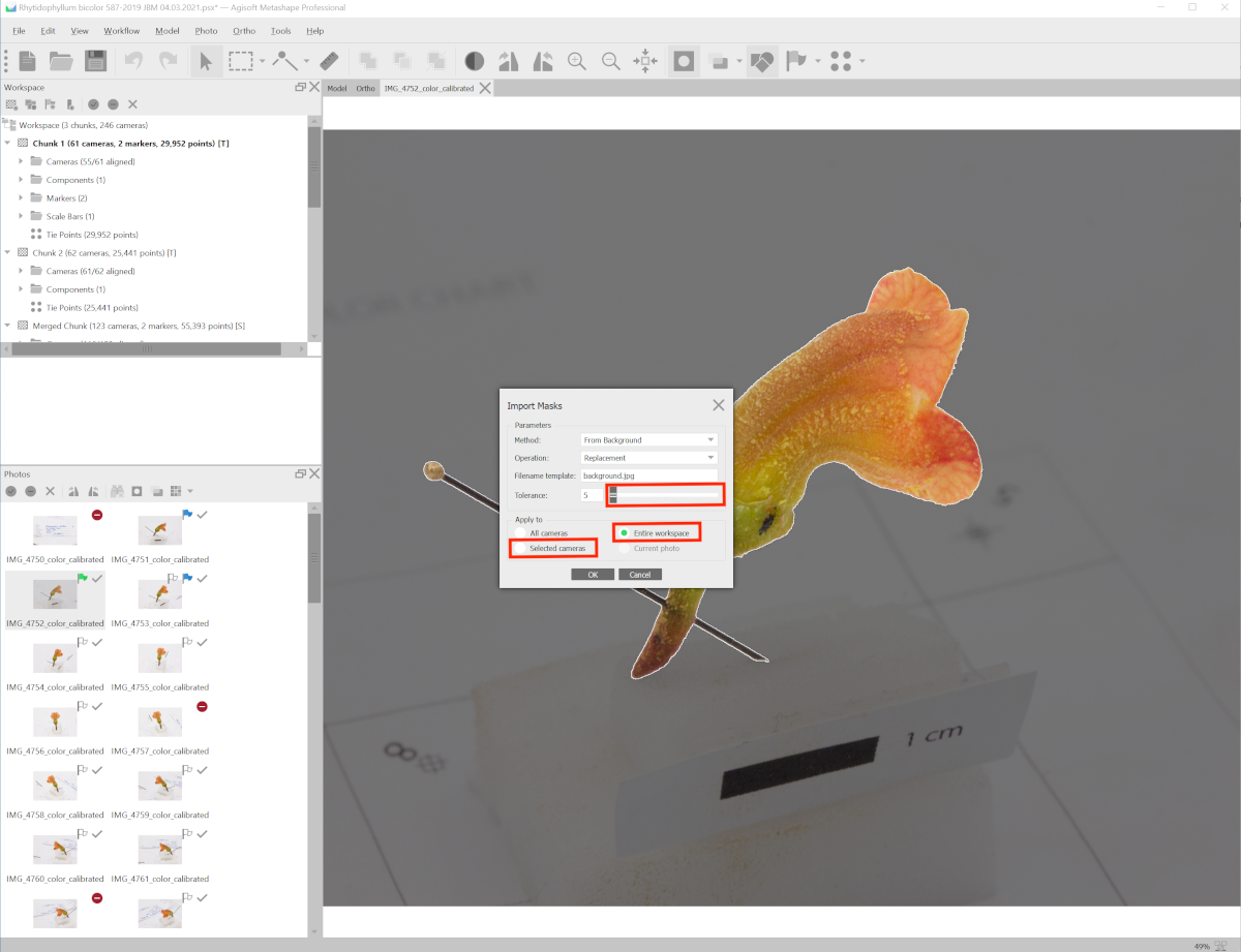
Figure 6.5: Import mask from a black image background.jpg, and select a tolerance value, to test on the selected camera (the image you right-clicked on). If the automatic mask is automatically well adjusted around the flower shape (darker gray around the flower), then apply to entire workspace (all the images).
Alternative masking method using Adobe Photoshop. It is also possible to use Adobe Photoshop to apply masks. We did not find particular improvements compared to the Agisoft Metashape approach.
Go to the file containing the pictures of chunk 1. Copy and paste this file, naming it accordingly (e.g. Chunk1-Background).
Go to Adobe Photoshop version 19.1 and up.
Make a copy of all of the photos you’ll be using and place them in a new folder labeled Chunk1-masks.
Then, you will need to create ONCE a Photoshop action, that will be subsequently reused (see Figures 6.6 to 6.9 below) :
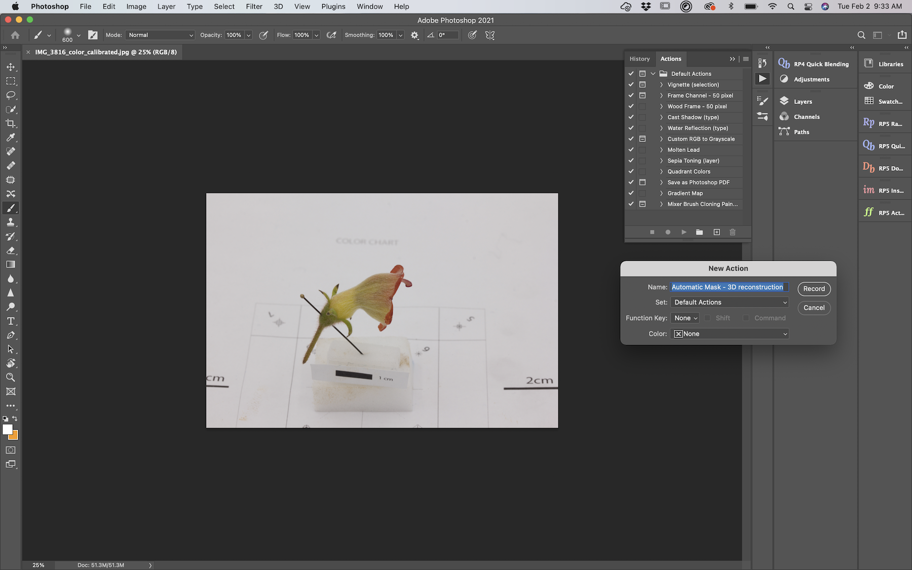
Figure 6.6: Record a new action called Automatic Mask - 3D reconstruction.
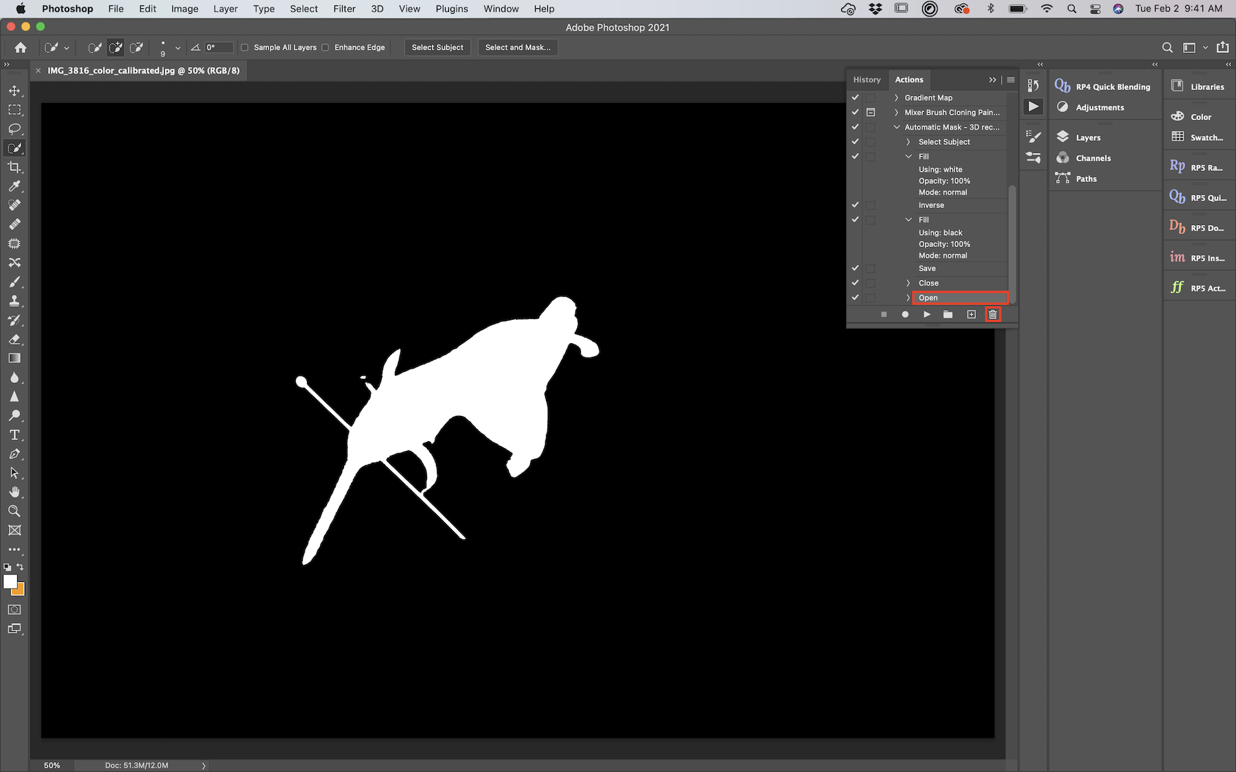
Figure 6.7: When you reopen your photo, don’t forget to remove this extra task in your action.
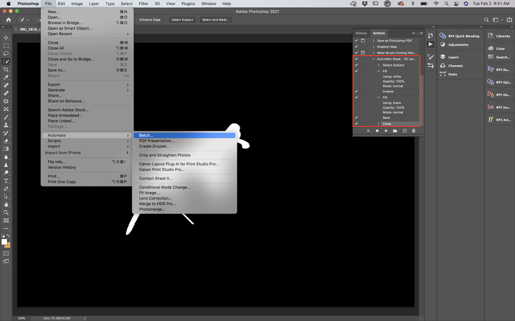
Figure 6.8: The action should include Select Subject, Fill, Inverse, Fill, Save, Close, and you can batch process this action to a specific folder of copied photos to create masks.
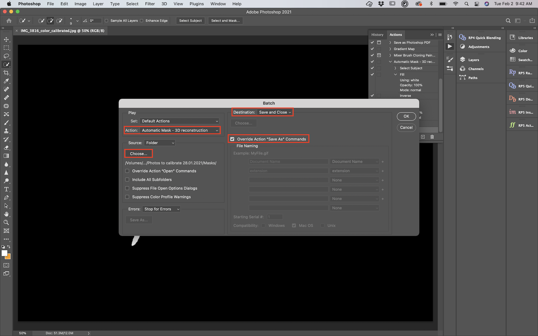
Figure 6.9: Apply the action to the folder of copied photos called Chunk1-masks.
Now you should have tranformed all your copied photos into masks, with the foreground object in white, and the background in black.
Go to Agisoft Metashape and right click on the first camera (photo) of chunk 1. Click on Masks > Import Masks and in the box that appears select method From file, operation Replacement. In Filename Template use filename.jpg. Select Apply to all cameras and then click OK.
Check the masks for touch ups.
6.6 Masks touch ups
The automatic application of masks at the previous steps is sometimes not entirely satisfactory for all photos. To add parts to the mask (i.e., remove them from the model) such as the foam block and the entomological pin, it is possible to select them using the selection tools and then add them using the respective Add Selection button (Figure 6.10). Similarly, you can remove or invert the selection with the buttons to the right of the Add Selection button.
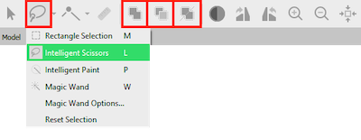
Figure 6.10: Selection tools and add selection to mask tool.
6.7 Image alignment
Click on the chunk you want to align, which could comprise several image/camera groups.
Make sure to disable photos you don’t want (e.g., the label photo, and blurry photos) and that the masks are clean.
Go to Workflow > Align Photos and put the accuracy on High or Very high (do not select the latter if you did focus stacking). To save some time, you can check Generic preselection in the section Advanced. Select Apply masks to Key points and click OK. Note that if you have applied the masks to only some photos, select Apply masks to tie points.
If you are aligning several chunks of photos, it is possible to run this job in batch for each chunk in Workflow > Batch Process > Add and select the Job type as Align Photos to apply to All Chunks or select specific ones (Figure 6.11).
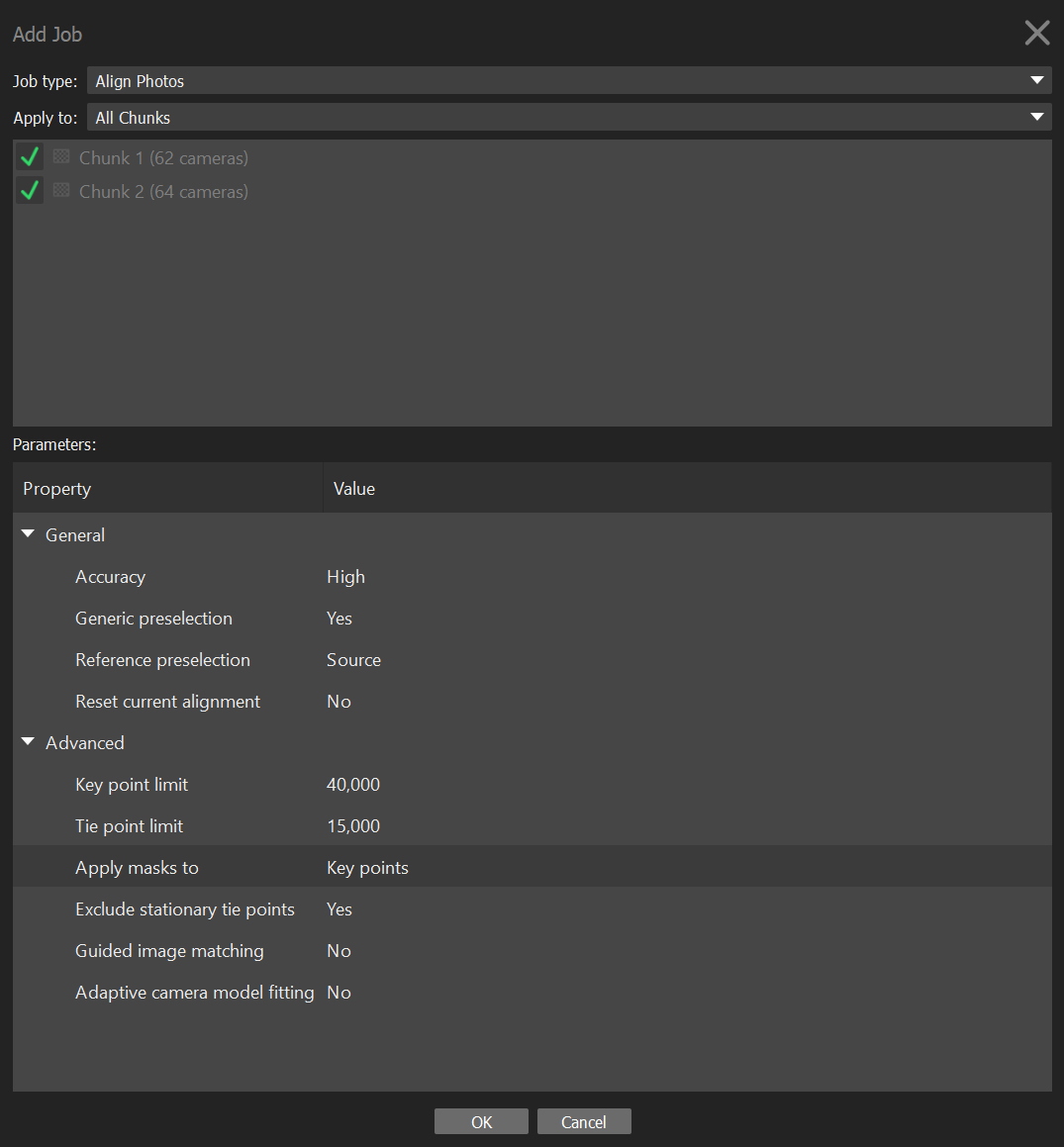
Figure 6.11: Align photos in multiple chunks.
Optional: Align using markers. If the images cannot align properly, it is possible to place homologous markers on the flower, defined as remarkable points (e.g., distinguishable pattern such as color dots on the corolla), or little pen marks at the surface of the flower when homologous markers lack. These points need to be clearly identifiable on all chunks. You will need at least 5 markers, ideally located at different areas of the flower (e.g., near the pedicel, sepal tips, petals). Do not use points from the background to align chunks as they are independent from the flower (the flower changes position relative to the background).
With the Navigation button selected (i.e., the “cursor” tool at the top), right click on the point you want to add a marker on.
Click on Place Marker > New Marker.
In the left panel, rename the marker accordingly. Make sure to use the same nomenclature on each chunk to be able to merge them according to their names.
To help the software recognize the markers, spread them on photos throughout the chunk (it is normally sufficient to manually place them on 2-3 photos and the software normally places them properly on the others, but make sure the markers are all properly placed).
If a marker is not visible in some photos, the flag of this marker should be white or the marker should be blocked on those specific photos. You can do that by right-clicking on the marker on these photos and select Remove Projection or Block Marker.
Repeat these step for each marker.
Go to Workflow > Align Photos and put the accuracy on High or Very high (the latter only for project without focus stacking). To save some time, you can check Generic preselection in the section Advanced. Select Apply masks to Key points and click OK. Note that if you have applied the masks to only some photos, select Apply masks to Tie points.
Optional: Alignment optimization using gradual selection and camera positions. If the camera alignment is not satisfactory, it is possible to clean the tie points obtained and try to re-align the cameras. For instance, in the tie points generated by the alignment, you can delete outlier and imprecise points (Figure 6.12 and 6.13):
In the top menu, click on Model and then Gradual Selection. Select Reconstruction uncertainty on Criterion and play with the Level value to remove the uncertain points. The higher the value, the worst is the point placed. Values between 30 and 10 generally give good results. Then OK. Press Delete (or fn + Backspace in Mac) on your keyboard to delete the selected points in red. You don’t need much more than 10,000 points for good photo alignments.
After removing uncertain points, go to View and click on Reference to make the reference panel visible if it is not already.
Click on the Optimize Cameras button (star icon) in the reference panel and in the Optimize Camera Alignment window, check all of the cameras in the General box and then click OK to optimize the camera posistions.
In Model > Gradual Selection, ensure that Reprojection error parameter is below 1. If it is not, check if the alignment runs well by clicking on the Show Cameras button (camera icon) on the top (the cameras needs to form a full circle around the flower). If the alignment fails, try to re-align photos by following step 3 (don’t forget to check the box Reset Current Alignment). If the alignment didn’t fail, go to Model > Gradual Selection > Reproduction error, and set the level to 1 and click OK. Then press Delete (or fn + Backspace in Mac).
Manually remove remaining outlier points using the selection tools.
Repeat these steps for each chunk.
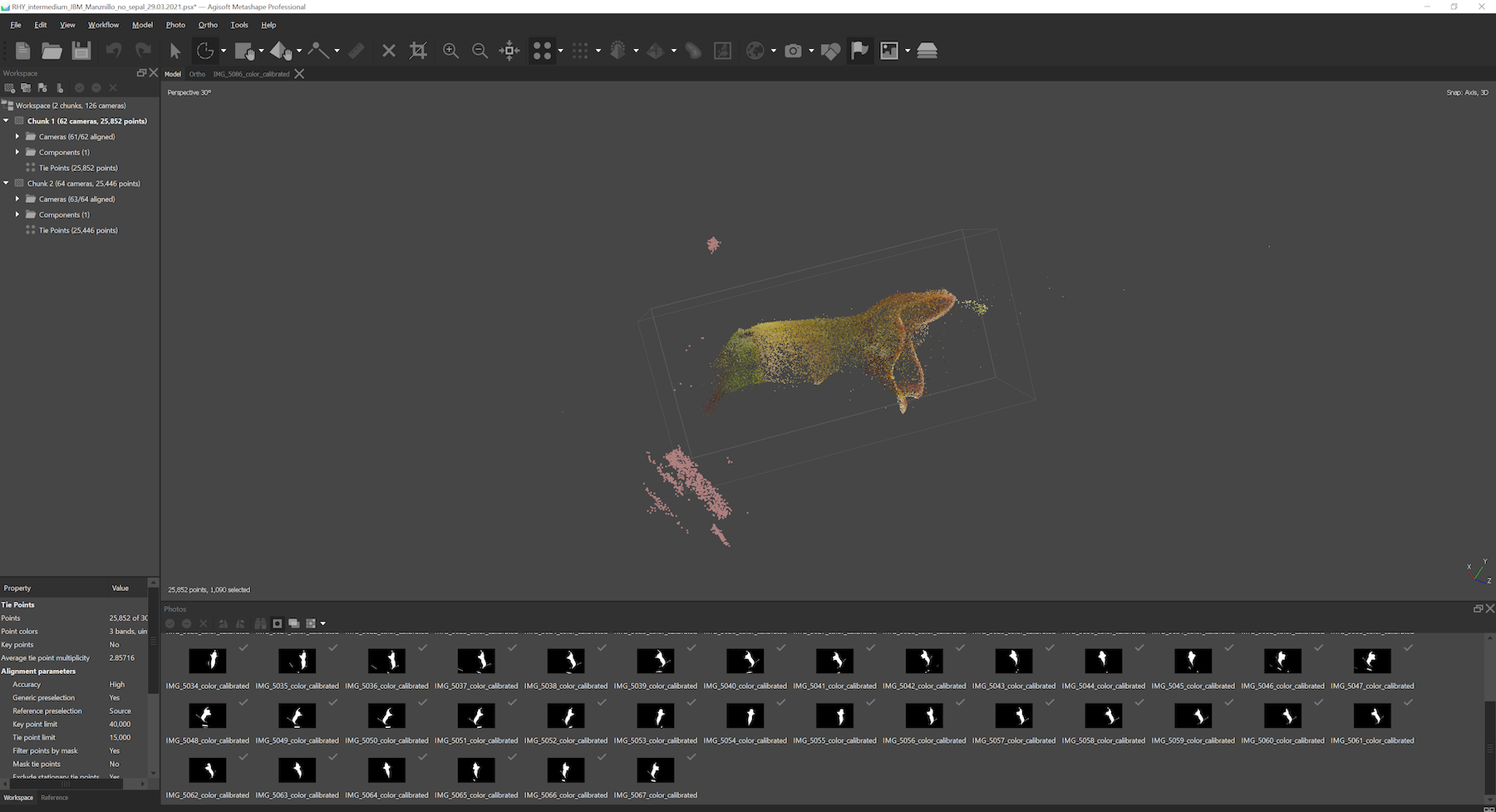
Figure 6.12: Use the selection tool to remove background points.
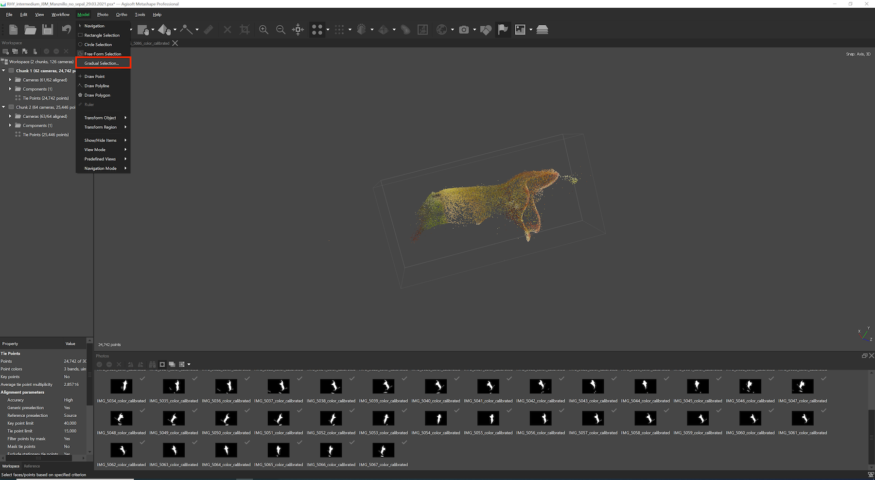
Figure 6.13: Use the gradual selection tool to remove additional mis-calculated points.
*Note: If the alignment fails using only one chunk and two or more camera groups, then it will be necessary to divide your job into several chunks. Each chunk should then contain photos from one flower position. Once the chunks are ready, you can proceed with the alignment following the previous steps.
6.8 Align chunks together
Note: This step is only necessary if your project is divided into several chunks.
At this step, it is important to align the different chunks with each other before they can be combined in a complete model. There are two ways to do this: using tie points (does not work every time) or using markers.
- To align using tie points:
Select one of the chunks that you would like to align.
Go to Workflow > Align Chunks, select all the chunks you want to align together and set the method as Point based (Figure 6.14).
Restrict the key points with masks.
Click on OK.
- To align using markers:
Place homologous markers on the flower, defined as remarkable points (e.g., distinguishable pattern such as color dots on the corolla), or little pen marks at the surface of the flower when homologous markers lack. These points need to be clearly identifiable on all chunks. You will need at least 5 markers, ideally located at different areas of the flower (e.g., near the pedicel, sepal tips, petals). Do not use points from the background to align chunks as they are independent from the flower (the flower changes position relative to the background).
With the Navigation button selected (i.e., the cursor icon tool), right click on the point you want to add a marker on.
Click on Place Marker > New Marker.
In the left panel, rename the marker accordingly. Make sure to use the same nomenclature on each chunk to be able to merge them according to their names.
To help the software recognize the markers, spread them on photos throughout the chunk (it is normally sufficient to manually place them on 2-3 photos and the software normally places them properly on the others, but make sure the markers are all properly placed).
If a marker is not visible in some photos, the flag of this marker should be white or the marker should be blocked on those specific photos. You can do that by right-clicking on the marker on these photos and select Remove Projection or Block Marker.
Repeat these step for each marker and each chunk.
Select one chunk. Go to Workflow > Align Chunks, select the chunks you want to align, set the method as Marker based and then click OK.
When the chunks are aligned, a [T] is put at the end of your chunk name to notify that it is transformed. You can check the alignment using the icon to show aligned chunks (i.e., the icon of layers on top of each others, Figure 6.15). The different chunks should be well aligned over the whole flower. If the alignment of your chunks is unsatisfactory, try to place more markers on recognizable features and spread across the whole flower. Additionally, you can manually align chunks using the tools to move the models in the space, but this is highly not recommended.
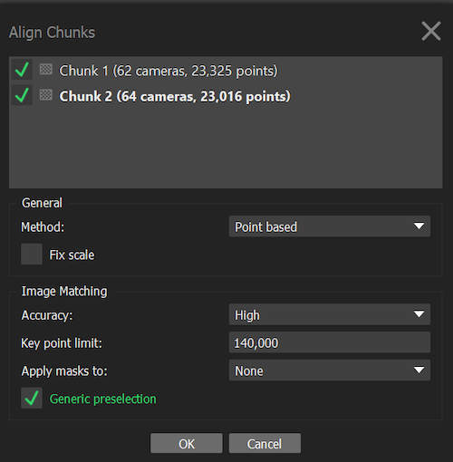
Figure 6.14: Align chunks.
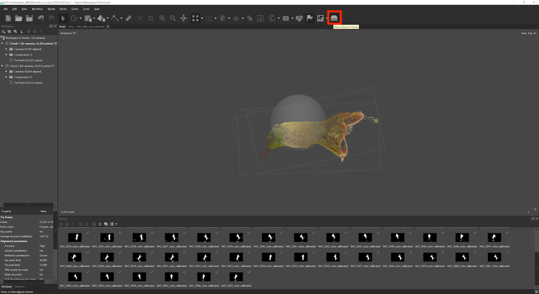
Figure 6.15: Show aligned chunks to verify their positions.
6.9 Merge chunks
Note: This step is only necessary if your project is divided into several chunks.
The next step is to merge chunks together when they are well aligned. Click on Workflow > Merge chunks, and merge using either the tie point method or the marker method depending on the option selected above.
6.10 Build 3D mesh
Select the chunk or the merged chunks for which you want to build a 3D mesh (model).
Go to Workflow > Build Mesh.
In the dialog box, make sure that Source Data is on Depth maps, Quality and Face Count on High (Figure 6.16). Note that although it is also possible to generate a mesh from a dense point cloud (which has to be built separately), the depth maps provide better results for objects with a high number of minor details.
Then go to Advanced, check Calculate vertex colors and click OK.
Once the mesh is produced, you should remove the pin and extra floating background parts using the selection tool. This will highlight the selection in red.
Verify your selection and press Delete (or fn + Backspace) to remove them.
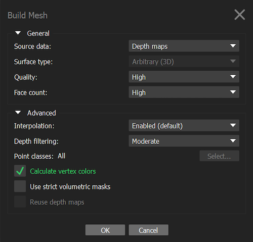
Figure 6.16: Build 3D mesh.
Our protocol merges the chunks to build a tie point model of all chunks before constructing a model for the merge chunk. We found that this is the best approach, although it is also possible to build models for each chunk separately and then merge these models to obtain a full model.
6.11 3D mesh touch ups
You can smooth the mesh by clicking on Tools, Mesh, Smooth Mesh. You can also duplicate a 3D model to save one intact (right click on it and un-check Use as default to keep it as an archived model). If you smooth a mesh, you can’t undo it.
You can fill holes in your mesh by clicking on Tools > Mesh > Close Holes. Note that if your holes are too big, the closing function can create unwanted structures. Similarly to smoothing, you cannot undo closing holes in the mesh. HOWEVER, this will remove the vertex colors in version 1.7.2, which we will need to place landmarks when doing the morphometrics.
6.12 Build texture
To build the texture go to Workflow > Build Texture, use the preset values and click OK.
6.13 Scaling
To scale the model, go to the pictures of your merged chunk and follow these steps:
On a picture displaying the scale bar, add new markers at each end of the scale bar and on a couple of additional photos.
In the left panel, select both markers, right click on them and select Create Scale Bar.
If the reference panel is not already visible on the left, go to View and click on Reference. Go to the reference panel, select the scale under Scale Bars and write 0.01 in the Distance (m) column (except if your scale bar has a different length, in which case, add the respective value of its length in meters).
Click on the Update Transform button in the reference panel (icon of two rotating arrows). This is an important step, because otherwise the scale will not be incorporated to your model.
To verify if the scale is taken into account, you can use the Ruler tool and select two points on your mesh to measure the distance between them.
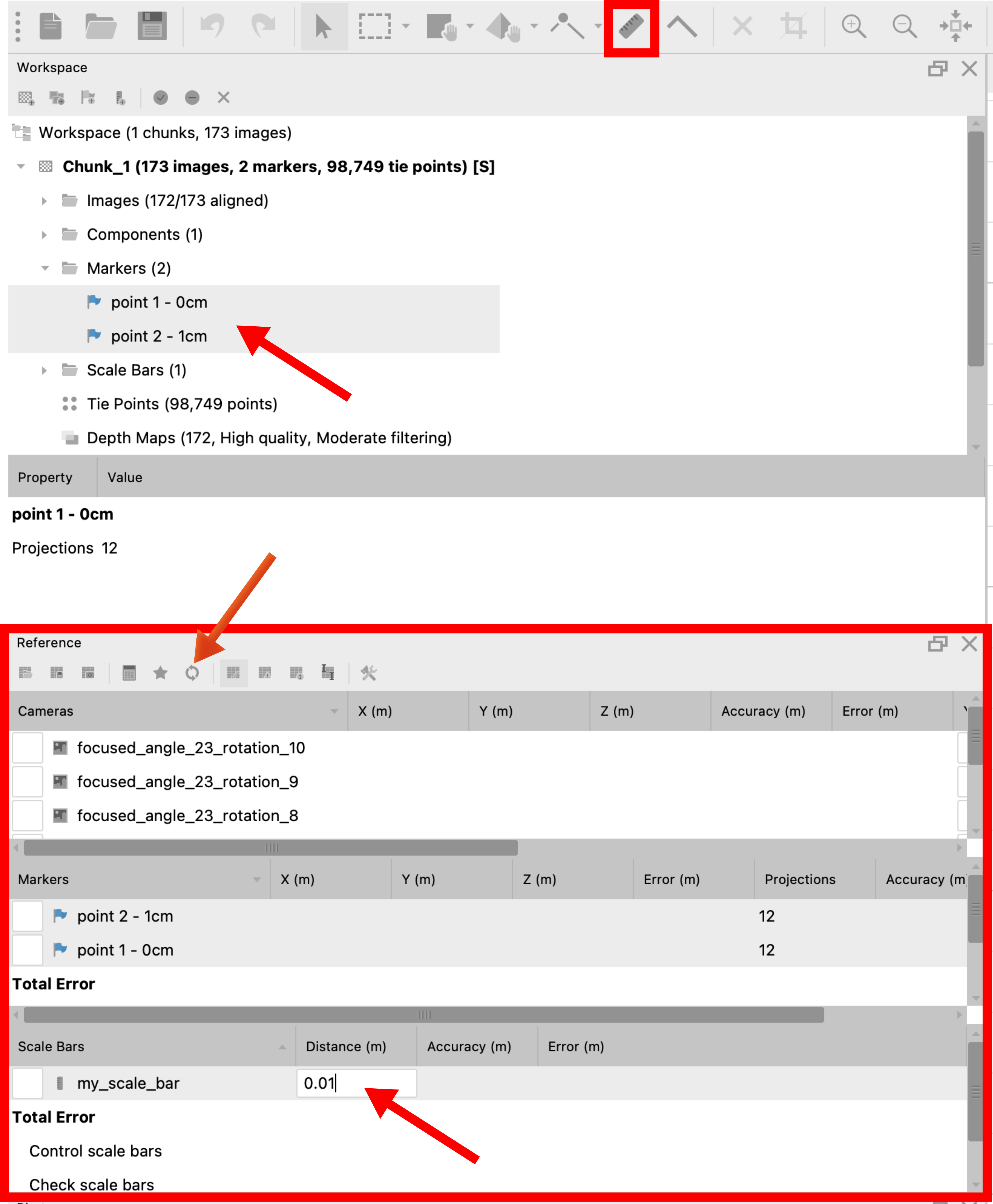
Figure 6.17: Scaling. Top arrow: Markers added at each end of the scale bar (i.e., at the 0 cm and 1 cm points). Middle Arrow: Update Transform button. Bottom arrow: Input of scale bar length in meters. Small red box (top): Ruler tool. Large red box (bottom): Reference panel.
6.14 Model orientation
In Metashape, be sure that Show Info and Show Grid in Model > Show/Hide Items are checked. You should see at the bottom right of the model panel the 3D axes.
Make sure that the scale is correct because changing it will affect the coordinates of the 3D model and you will need to re-orient it. You can verify the scale using the Ruler tool.
Use the Navigation tool to orient these 3D axes (x should be at 0° and y should be at 90°; Figure 6.18).
Once you orient the 3D axes in the wanted direction, you can then use the tool Move Object to put the flower in the center of the grid (the cross in the center point of the grid should be hidden in the central point of the 3D model; Figure 6.18 and Figure 6.19).
To orient the model, use the Rotate Object. The model should be facing the right side of the grid (the direction of the x axis; Figure 6.18 and Figure 6.19).
Orient the binding box as well, using the Move Region, Resize Region and Rotate Region tools. The side with the cross on the box should be on the ventral side of the flower, and the side with the two dashes should be facing the opening of the flower. Note that depending on the software you use to open the model, the first view orientation may change when you open the final object file (Figure 6.20).
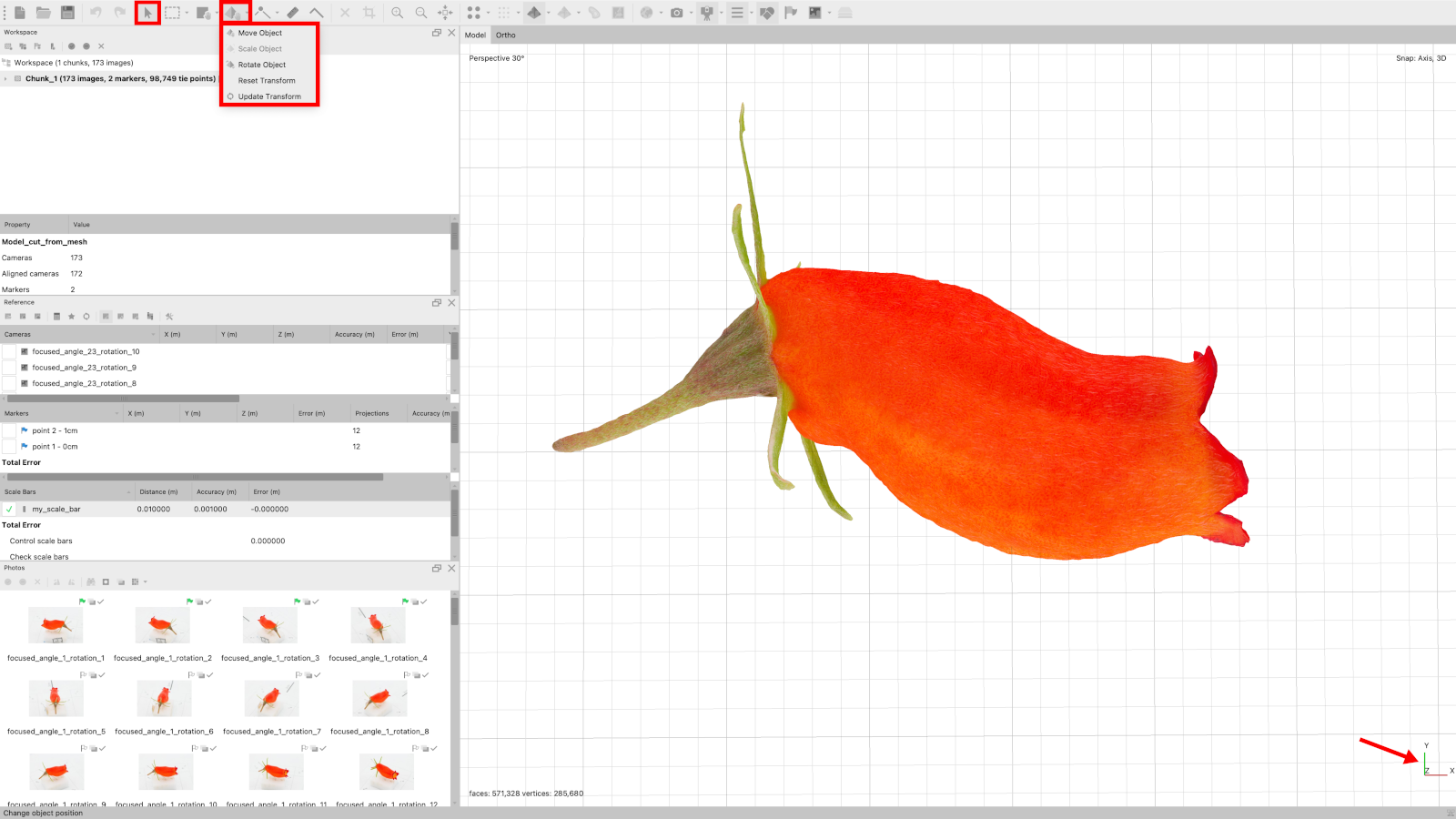
Figure 6.18: Object (model) orientation tools. Left box: Navigation tool. Left box group: Object orientation tools. Arrow: Desired 3D axes orientation.
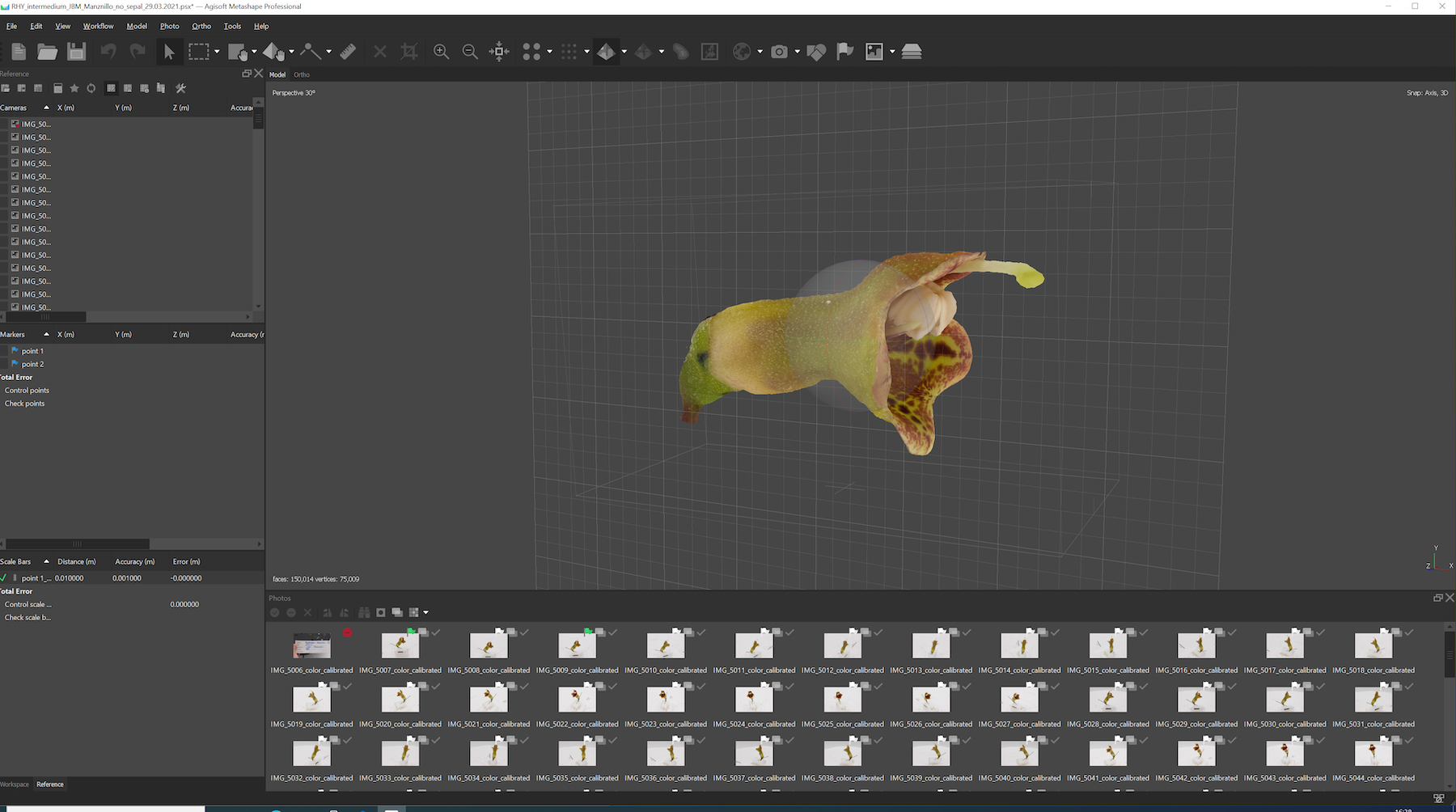
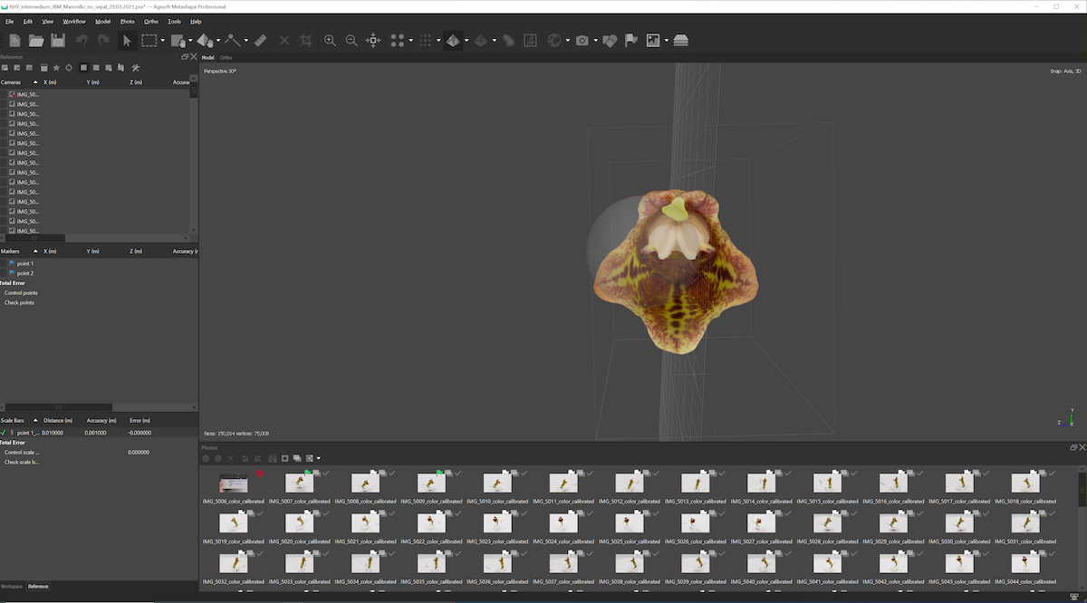
Figure 6.19: Desired model orientation on the grid.
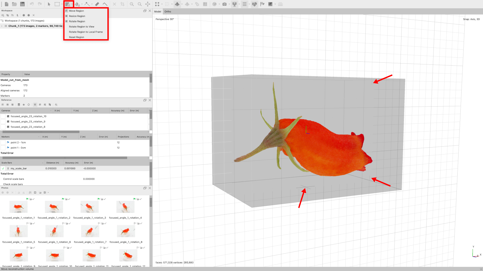
Figure 6.20: Binding box orientation tools. Box group: Binding box orientation tools. Arrows: The cross and the two dashes on two different sides of the binding box.
6.15 Export model and texture
You can export your 3D model by clicking on File > Export > Export Model.
Name your model.
Choose .ply as the extension.
In the dialog box, tick the Vertex colors. This option will allow you to get color on the actual 3D model.
Select Export texture as PNG.
Make sure to export the texture with transparency, by ticking the Write alpha channel or Save alpha channel option (depending on the Agisoft Metashape version). The texture is a separate file with detailed color information that is wrapped on the model.
Click on OK.